A circuit is simply a closed loop where energy flows from a source, through a load, and back. In Module 1, students build that loop by hand with real modules — then measure it with the instruments in the LogiqLab app. Here are the first two labs, exactly as students run them.
Both labs use the Main Board panel and the DC Power module (three 1.5 V AAA batteries, mind the polarity). No prior experience needed. The point isn't just to wire something that works — it's to see and measurewhat's happening, and understand why.
Lab 1 — First Analog Circuit
Build it
On the Main Board, connect the DC Power module to a load. Use the DC Motor module first, then the LED element. This is a complete, closed circuit — real modules, not a simulation.
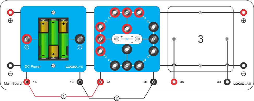
Observe it: The motor shaft spins clockwise — current flows from the positive to the negative contact. Reverse the cables and it spins the other way. Swap in the LED: it lights only when connected in the correct direction, and stays dark when reversed.
The takeaway students reach on their own: a load only works when current flows through a closed circuit, and some devices depend on the direction of that current. Open any cable while the motor spins and it stops instantly — the voltage is still there, but the current is gone.
Lab 2 — First Measurement
Build it
Set the DC Power module on the Main Board and connect the measurement leads (red and black banana cables) across its terminals.
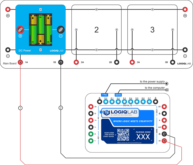
Measure it: Open the LogiqLab Tools app, launch the Digital Multimeter, select DC voltage mode and the 5 V range. Read the voltage across the terminals — it's positive. Now reverse the leads: the same magnitude appears, but with a negative sign.
Here's the understanding students build: the sign of a voltage reading tells you how the leads are oriented relative to the circuit — not that the voltage changed. It's their first real measurement with a real instrument, and the foundation for every lab that follows.
The LogiqLab difference
Building the circuit is half of it. Measuring it — with real instruments that run right in the app — is where understanding starts. Every LogiqLab lab closes that loop.
These two labs open a seven-module course spanning DC and AC circuits, capacitors and inductors, power conversion, and transistors — 18 hands-on analog labs in all, each aligned to NGSS and California CTE standards.